
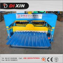
used cut to length line for sale
Basic Info
Model No.: Cut to length,slitting line
Product Description
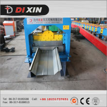
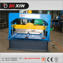
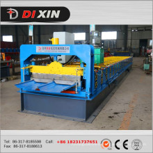
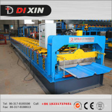
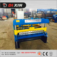
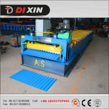
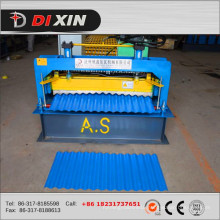
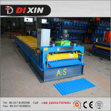
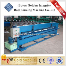
slitting line machine,cut to length line 1.Machine pictures 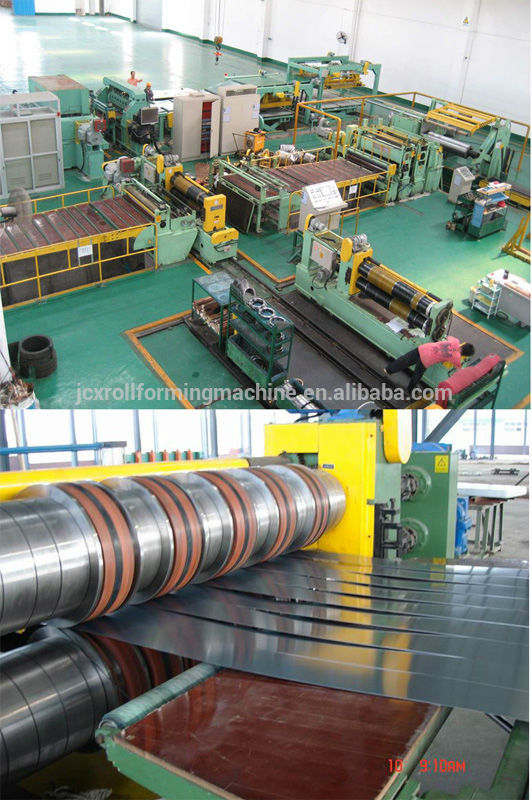 2.General introduction Slitting line can do uncoiling, slitting and recoiling works, make coil steel to any needed width coil steel. It mainly includes coil car, uncoiler, coil guide, Slitting Machine, scrap winder, tension unit, recoiler and coil car, hydraulic system, Etc. It mainly used in coil or hot rolling carbon steel, silicon steel and all the other kinds of metal materials with surface spreading.
This line can be adjusted to do recoiling or dividing work to meet customer’s demand. 3.Technical information:
Material: Hot roll steel and cold roll
Material weight: Max 15 T
Material thickness: 0.5 mm – 3 mm
Material width: 500-max 1600mm
Material inner diameter: 508mm
Material outside diameter: 1500mm
Slitting speed: 120m/min
Width tolerance: +/-0.1 mm
Set up Position : from left to right
Total power: about 200KW. 4. Machine parts in the working line a) coil car
b) decoiler
c) Pinch roll
d) Shearing Machine
e) Loop table I f) coil guide and pinch roll
g) Slitting machine
h) scrap winder (both sides)
i) Loop table II
j) separator and tension table
k) Deflector roll and exit threading table
l) Recoiler
m) Over arm separator in the recoiler.
n) Exit coil car for recoiler
o) Hydraulic system
p) pneumatic system
q) electrical control system 5.Technical description Entry coil car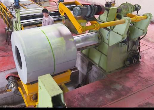 Application:
The entry coil car will be hydraulically actuated. It will be used to Traverse and load coil onto the mandrel of the decoiler.
To gain time while working, new coil is loaded to the coil car and lifted to the mandrel position by hydraulic lift and the coil car start to move horizontally let the mandrel go inside through the coil Then the loading car moves to the park position. Construction:
The coil car is a fabricated body of prime materials; mounted on hardened wheels and axles with spherical roller Bearing. The lifting face must be of ‘V’ shaped design. The cradle (i.e. V – Shape frame) is raised and lowered by four Colum steel and a hydraulic cylinders. The coil car traverse is accomplished by a electrical motor with a gear and pinion drive.
Technical Data:
Type of Coil Car : rail Type
Lift Capacity : 15 Tons (Max.)
Lift / Lower function : By hydraulic cylinders with four Column 6.decoiler Application:
The decoiler can handle the coil and be capable of feeding the coil into the slitting Line, and also rewinding partially consumed coils, so they can be re-strapped whilst still on the mandrel, before returning to Coil Storage Facility for use at a later date. Construction:
The coil is handling and collapsed by double head. Steel fabricated duly machined, mounted on heavy duty shafts on anti-friction bearings. The individual body and the whole housing are fabricated by steel construction.
Pneumatic controlled braking system is provided to minimize over running of the coil with tension. A brake is provided to stop the line whenever the line stops for any reason. Technical Data:
Capacity : 15 Tons (Max.)
Inner Diameter : Ø508mm
expansion : hydraulic cylinder
Coil OD : 1500mm Snubber Roller (Guiding Equipment) The decoiler’s function is to take a new roll of metal and in a coordinated fashion feed the material into the pinch roll and shear. This is accomplished by a brake with a motor driving the deccoiler. When a brake is used, the material typically feeds via a thread-up motor directly into the pinch roll . Once the pinch roll has the material, the brake holds tension in the material and the motor turns off. The operator sets brake tension controls brake tension. A motor is used on the uncoiler, the material goes directly into the pinch roll as described above and the decoiler drive acts as both the thread up motor and the hold-back brake. Application:
Anti coil break roll and guiding the coil to the slitting line.
It will operate with the decoiler and the coil peeler to feed-up the coil end. The roll will be bear on the top of the coil, restraining the outer wrap and driving it forward.
A motor is driven Snubber Roller, (pressure roller) to prevent the coil from clock springing when the coil retention straps are removed. Grooves are required on the roll, to enable re-strapping of partially consumed coils when they are rewound on the mandrel. The roll will be capable of driving in both feed and retrieve directions.
Construction:
Snubber Roller is made out of Steel Pipe with suitable journals duly machined to be mounted on anti-friction bearings. The Roll is coated with poly rubber. roll is driven by electrical motor with chain & sprocket system. Roll and its Drive system is fitted on fabricated structure which in turn is mounted on the adjacent structure of Pinch Roll body. Actuation of arm is by hydraulic cylinder. 7.Peeler coil entry table Application:
A hydraulically actuated peeling spade extending to the coil tongue on the Un-Coiler to “peel off” the leading edge of the coil and then retract to the Entry Pinch Rolls of pinch roll. This enables the operator to remotely thread the leading edge of the coil without having to manually handle the coil. The operator activates the positioning of the peeling spade at either end by hydraulic cylinders, actuated by “push button” controls.
Construction:
Welded steel plate construction pivot mounted from entry pinch roll. Telescoping and positioned by hydraulic cylinders 8. Pinch roll Application:
A pinch roll with be provided to pull the strip from the payoff reel. The pinch roll unit will operated in conjunction with coil peeler to deflect strip into the shear and establish the entry pass line for payoff operation. Construction:
The body of the Pinch Roll is fabricated out of prime plates and machined to house the roll assemblies.
Pinch rolls are provided to pull the strip from the coil mounted on the decoiler. Adequately sized pinch rolls are provided at entry of the shear to ensure that the sheet is not damaged by the pinching forces.
The pinch roll are capable of being lowered or raised during threading to accept the leading edge of the coil. The top roll must deflect the strip from Uncoiler to suit the pass line and actuate up and down by means of a pair of hydraulic cylinders.
The pinching force developed by the hydraulic cylinders must present slippage between pinch rolls and sheet.
Rolls are driven via AC drives variable speed motor, gearbox, universal couplings. 9. Hydraulic Tip shear Application:
The shear will be used for removing off gauge or damaged material and squaring the lead end of the coil.
Construction:
Down cut shear actuated by hydraulic cylinders. Cylinder connected by rack and pinion cross shaft mechanism for equalization.
Structure : Steel fabrication
Cutting Power : Hydraulic cylinder 10. Entry loop table I Application
The entry loop will create a buffer zone for easier centering for next stage process. Light source and sensors is provided for sensing the loop position.
Construction:
A hydraulic operated threading table is provided for initial threading. Quadrant table is provided at the entry and exit of the loop bridge. Hinge Table is actuated (i.e. Swinging) with hydraulic cylinder.
Type : bridge table.
Structure : Steel fabrication
Moving power : Hydraulic cylinder
Loop position sensing : By photo sensors 11. Mechanical side guide and pinch roll A. Side guide rolls
Application:
Width shall be adjustable manually with hand-wheel and movement shall be
accomplished by guiding shaft with Left Hand & Right Hand Thread on the same shaft. Construction:
A fabricated body with roller mounted vertically at two sides (2 Nos. rollers each side). Roller is mounted vertically.
B. Pinch roll
Application
The pinch roll locate at the exit end of the side guide will be provided for smooth threading into slitter.
Type : Positioning by cylinders 12. Slitter machine.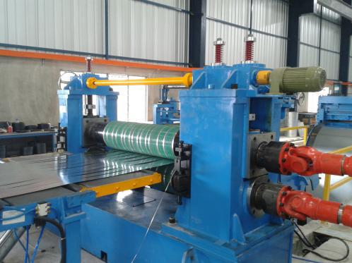 Application
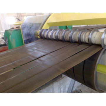
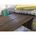
The slitter stand will be provided to slit strip to desired width. The slitter stand will be a heavy duty design, driven through universal joints from multiple output gear box. Construction
A machine for slitting metal sheet has a bridge-type frame provided with upper and lower beams supported on posts. In the space between the two beams are upper and lower powered arbors, Each powered arbor supports and turns several knives which are mounted on hubs along those arbors, and these knives when not needed may be moved.
And a series of spacer rings precisely locate the slitter knives on each arbor. The machine cut the sheet width according to the spacer to adjust. Of course, the spacer has the thickness of specification, such as 5mm, 10mm, 15mm, 20mm, 28mm, 30mm etc. Slitting arbor material: we use 42CrMo steel, good process, quenched and tempered, processing, grinding and chromed finished and grinding again, etc. make sure the axle Non-deformation in the heavy working condition. Slitting head: the head and upper bearing seat are casting steel, the lower bearing seat is forged quenching and processed, a fixed housing and a movable housing to support the arbors / bearings and sleeves. Movable housing can be moved out using screw motor mechanism, for inserting slitter tooling as per the slitting schedule. The both arbors have the long key to lock the cutter.
The upper arbor is lifted by worm gear and motorize. Both the arbors are driven by motor through a gear reducer cum pinion stand and universal shaft.
The complete slitter head assembly as explained above is fitted on fixed frame grouted to the concrete foundation.
The slitting head is a pair of rolls nipped together. These rolls have the knives in them that actually cut the metal.
Power system: the slitting machine equip with motor, gear box and universal shaft to set up functioning. the slitter is driven by a thread-up variable speed motor that have looping pits and multi-modes of operation. Type : Round knife cutting.
Structure : Fabricated Steel, 42CrMo steel slitter arbor
arbor diameter : 200mmx2 Cast steel choke
Vertical adjustment :Motorizes anti-backlash worm gear for Vertical adjustment
Slitter Stand locking : Motorize Lubricant : Grease gun
Construction: : Fully enclosed helical gears, shaft rotate in roller bearings, and coupling to the motor.
Motor : AC 75 KW
Lubricant : Oil bath 13. Scrap winders ( both sides) Application
The scrap winder is provided to wind up the edge trim scrap per stand, Also a scrap winder machine and scrap removal system, which shall automatically process and remove the waste from the line without any interruption to the line operations.
Construction:
Two winder heads one for each side will be mounted on the side of the carry over
table. Each Heads’winding tension can be adjusted with a spring mounted on arbor. All frameworks will be heavy welded steel fabrications.
Drive system
One variable speed motor will drive both winder heads. The motor is sized so that ample torque is available to wind the heaviest material at stall conditions. Therefore, winder speed is kept synchronous with line speed over the entire range from zero to top speed. 14. Entry loop table II Application
The entry loop will create a buffer zone for easier centering for next stage process. Light source and sensors is provided for sensing the loop position. Construction:
A hydraulic operated threading table is provided for initial threading. Quadrant table is provided at the entry and exit of the loop bridge. Hinge Table is actuated (i.e. Swinging) with hydraulic cylinder.
Type : bridge table
Structure : Steel fabrication
Moving power : Hydraulic cylinder
Loop position sensing : By photo sensors
Lubricant : Grease gun 15, Strip separator and tension unit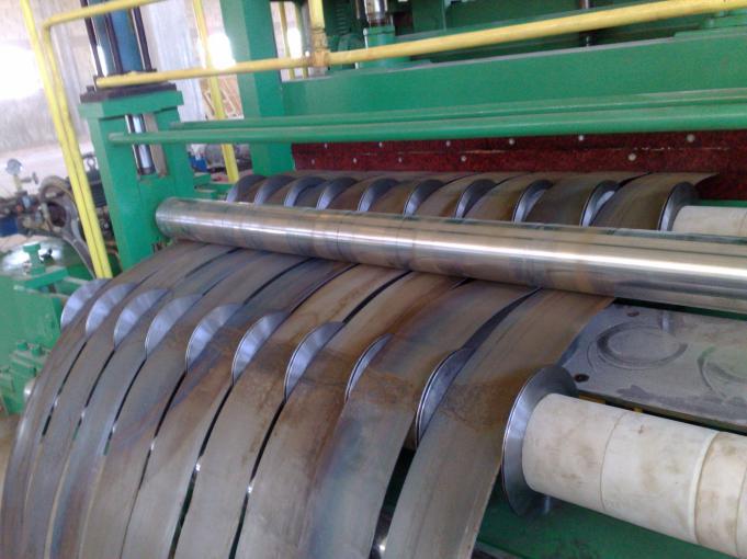 A. Strip separator. Application Separating slit strips so that they don’t interfere with each other. The tension unit is there to provide tension for recoiling. The separator roller can be move out for installing the separated disc. B. Tension unit Tension unit creates the tension for the recoiler to pull against after the exit loop. This tension can be created via friction pads (top and bottom) that hydraulically press together to hold the strip back from the recoiler. Felt pad type with wooden pad, high performance spring in bed into the upper side of the tension unit, to ensure even force is applied across the whole strip. Power: Tension power is generated from 2 hydraulic cylinders. 16. Deflector roll and exit threading table A. Deflector roll Application The deflector roll is placed right before the recoiler. It helps to maintain the pass line at a fixed level. A powered smaller roll will help to threading. Structure : Steel fabrication Deflector roll : Ø 400mm Roll material : Hard chromium plated Drive roll surface : Hard polyurethane Lubricant : Grease gun B. Threading table Application A hinged fabricated plate structure raised and lowered by a hydraulic cylinder for guiding the strip into the gripper slot of the mandrel drum of the recoiler . Structure : Steel fabrication Table moving power : Hydraulic cylinder Lubricant :Grease gun 17. Recoiler with push off plate& outboard bearing support
 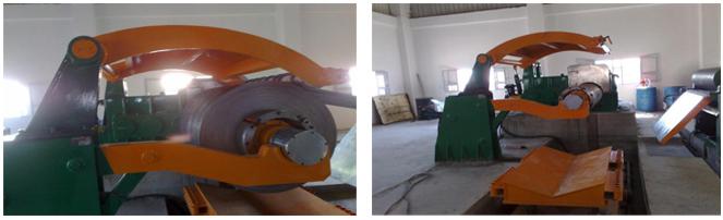 A. RECOILER Application: The recoiler is provided to rewind the strip after slitting. The recoiler section of the metal slitting line produces the coils of slitted material that are typically banded and shipped to customers for a variety of applications. The recoiler is the master section for the slitting line and always includes a variable speed drive. There is usually a “drag tach” that mounts after the tension stand and gives strip speed feedback. This feedback is used by the recoiler drive to maintain constant strip speed as the recoiled roll gets bigger. Construction: The coil is handling and collapsed and expansion by hydraulic expansion. Steel fabricated duly machined, mounted on heavy duty shafts on anti-friction bearings. It is collapsed by Hydraulic cylinders. The individual body and the whole housing are fabricated steel construction. Mandrel equipped with hydraulic actuated 4 segments sliding wedge for expansion. Pneumatic controlled braking system is provided to minimize over running of the coil. An additional brake is provided to stop the line whenever the line stops for any reason. Expanding power : Rotary hydraulic cylinder Expansion range : Ø 460mm~ Ø 520 mm Outer Diameter : Ø 1500mm Mandrel Surface : Chromium plated Load capacity : Max. 15 Tons (Max.) B. Gripper Activate by the hydraulic and arranged for over winding. Hardened steel gripper face. Gear box. Construction: Fully enclosed helical gears, shaft rotate in roller bearings, and coupling to the motor Motor : 110KW Lubricant : Oil bath C. Push off plate Construction: Fabricated steel large face pushes on the coil side area. Plate activated by a hydraulic cylinder, operated by double solenoid valve. Power : Hydraulic cylinder Plate surface : Chromium plated 18. Over arm separator in the recoiler.
  Application Separating slit strips so that they don’t interfere with each other. Type : Over arm type Structure : Steel fabrication Pressing power : Hydraulic cylinder Separator Shaft : Ø 100mm Pressure adjustment : Pressure control valve Lubricant : Grease 19. Pit type exit coil car
 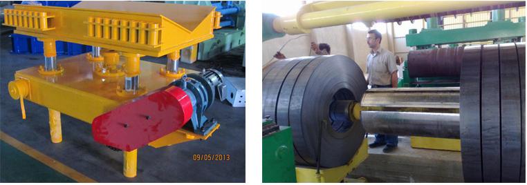 Application The entry coil car will be hydraulically actuated. It will be used to Traverse and load coil onto the mandrel of the Recoiler. The coil car is a fabricated body of prime materials; mounted on hardened wheels and axles with spherical roller Bearing. The lifting face must be of ‘V’ shaped design. The cradle (i.e. V – Shape frame) is raised and lowered by four Colum steel and a hydraulic cylinders. The coil car traverse is accomplished by a electrical motor with a gear and pinion drive. Technical Data: Type of Coil Car : rail Type Lift Capacity : 15 Tons (Max.) Lift / Lower function : By hydraulic cylinders with four Colum Lubricant: Grease gun. 20.Hydraulic System One hydraulic Power Pack with stand-by pump is provided for the hydraulic functions in the line and it will remain in our scope of supply which is as follows. Hydraulic Power Pack is consist of: • Standby pumping unit Control valves: • The control valves for each equipment or group of equipment is mounted on the equipment and piping. • Each control valve / group of valves is provided with an isolating valve on the ’P’ line and Check valve on the ‘T’ line for ease of maintenance. • Pressure switch is provided for Uncoiler expansion cylinder for interlock 21.Pneumatic systems Pneumatic controls is used at various equipments for actuations. Pneumatic control valves is mounted on individual equipment and piped. The pneumatic systems is consist of following. • The piping on equipment consist of flexible piping with push in type of fittings for easy maintenance. 22.Electrical System: Standard Application Modules Kingjime machinery Automation has years of experience in designing systems for metal slitting lines – both new machines and retrofits. We’ve taken this experience and developed standard application modules; these modules are field-proven, so you get the advantages of reduced engineering and start-up time. Yet we’ve included the ability to customize these modules for your machine control logic and options. Each option includes the software, hardware and drawings to implement this function. Available Modules: _ Slitting Line Master – This module is required for each line and is the master for the slitting line. It includes software and hardware for control of the recoiler and operator interface. Functions include: _ Line start/stop _ Line speed set and adjust _ Line fast stop _ Line E-stop/reset _ Recoiler jog fwd/rev _ Recoiler mandrel expand/hold/collapse _ Uncoiler Control – There are a variety of options available to control either a mechanical brake or a variable speed drive on the uncoiler. Functions include: _ Uncoiler tension set _ Uncoiler jog fwd/rev _ Uncoiler over/under _ Uncoiler mandrel expand/hold/collapse _ Hold-down roll raise/lower _ Uncoiler thread table raise/lower Slitter Control – There are a variety of options available to control either a mechanical or a variable speed drive on the slitter. Functions include: _ Slitter load/loop adjust _ Slitter jog fwd/rev _ Looping pit raise/lower _ Tight/loop select Drives and Motors We have available a wide choice of features and configurations available to fit each application and environment. Electrical System supply will remain in our scope and is provided with following list. The electrical system is consist of following motors and its controls PLC and touch panel from Siemens The machine will be included the following accessories from supplier in main shipment The knife : 20 pieces of knives from the supplier Spacer: supply from the supplier Separator and disc from the supplier air pipes from the supplier. Wire from the supplier. Field Elements: Foundation Bolts: Foundation Bolts remain in our scope. We will supply only foundation bolt details with Drugs of foundation Layout & Foundation Bolts. Inter connecting Piping: Hydraulic & Pneumatic pipes and fittings will be supplied by manufacturer TRAINING in the installation the machine If you are tired of those Chinese bad machines, and want to buy high quality machines in China, Just stop searching!we are your best choice!We offer you quality machine with good price! Contact Person:presley.xu Skype:Presley.xu Mob:+86 18732755439 Contact us if you need more details on Used Cut to Length Line for Sale. We are ready to answer your questions on packaging, logistics, certification or any other aspects about Used Slitting Line for Sale、Used Complete Production Line for Sale. If these products fail to match your need, please contact us and we would like to provide relevant information.
 2.General introduction Slitting line can do uncoiling, slitting and recoiling works, make coil steel to any needed width coil steel. It mainly includes coil car, uncoiler, coil guide, Slitting Machine, scrap winder, tension unit, recoiler and coil car, hydraulic system, Etc. It mainly used in coil or hot rolling carbon steel, silicon steel and all the other kinds of metal materials with surface spreading.
This line can be adjusted to do recoiling or dividing work to meet customer’s demand. 3.Technical information:
Material: Hot roll steel and cold roll
Material weight: Max 15 T
Material thickness: 0.5 mm – 3 mm
Material width: 500-max 1600mm
Material inner diameter: 508mm
Material outside diameter: 1500mm
Slitting speed: 120m/min
Width tolerance: +/-0.1 mm
Set up Position : from left to right
Total power: about 200KW. 4. Machine parts in the working line a) coil car
b) decoiler
c) Pinch roll
d) Shearing Machine
e) Loop table I f) coil guide and pinch roll
g) Slitting machine
h) scrap winder (both sides)
i) Loop table II
j) separator and tension table
k) Deflector roll and exit threading table
l) Recoiler
m) Over arm separator in the recoiler.
n) Exit coil car for recoiler
o) Hydraulic system
p) pneumatic system
q) electrical control system 5.Technical description Entry coil car
 Application:
The entry coil car will be hydraulically actuated. It will be used to Traverse and load coil onto the mandrel of the decoiler.
To gain time while working, new coil is loaded to the coil car and lifted to the mandrel position by hydraulic lift and the coil car start to move horizontally let the mandrel go inside through the coil Then the loading car moves to the park position. Construction:
The coil car is a fabricated body of prime materials; mounted on hardened wheels and axles with spherical roller Bearing. The lifting face must be of ‘V’ shaped design. The cradle (i.e. V – Shape frame) is raised and lowered by four Colum steel and a hydraulic cylinders. The coil car traverse is accomplished by a electrical motor with a gear and pinion drive.
Technical Data:
Type of Coil Car : rail Type
Lift Capacity : 15 Tons (Max.)
Lift / Lower function : By hydraulic cylinders with four Column 6.decoiler
 Application:
 The decoiler can handle the coil and be capable of feeding the coil into the slitting Line, and also rewinding partially consumed coils, so they can be re-strapped whilst still on the mandrel, before returning to Coil Storage Facility for use at a later date. Construction:
The coil is handling and collapsed by double head. Steel fabricated duly machined, mounted on heavy duty shafts on anti-friction bearings. The individual body and the whole housing are fabricated by steel construction.
Pneumatic controlled braking system is provided to minimize over running of the coil with tension. A brake is provided to stop the line whenever the line stops for any reason. Technical Data:
Capacity : 15 Tons (Max.)
Inner Diameter : Ø508mm
expansion : hydraulic cylinder
Coil OD : 1500mm Snubber Roller (Guiding Equipment) The decoiler’s function is to take a new roll of metal and in a coordinated fashion feed the material into the pinch roll and shear. This is accomplished by a brake with a motor driving the deccoiler. When a brake is used, the material typically feeds via a thread-up motor directly into the pinch roll . Once the pinch roll has the material, the brake holds tension in the material and the motor turns off. The operator sets brake tension controls brake tension. A motor is used on the uncoiler, the material goes directly into the pinch roll as described above and the decoiler drive acts as both the thread up motor and the hold-back brake. Application:
Anti coil break roll and guiding the coil to the slitting line.
It will operate with the decoiler and the coil peeler to feed-up the coil end. The roll will be bear on the top of the coil, restraining the outer wrap and driving it forward.
A motor is driven Snubber Roller, (pressure roller) to prevent the coil from clock springing when the coil retention straps are removed. Grooves are required on the roll, to enable re-strapping of partially consumed coils when they are rewound on the mandrel. The roll will be capable of driving in both feed and retrieve directions.
Construction:
Snubber Roller is made out of Steel Pipe with suitable journals duly machined to be mounted on anti-friction bearings. The Roll is coated with poly rubber. roll is driven by electrical motor with chain & sprocket system. Roll and its Drive system is fitted on fabricated structure which in turn is mounted on the adjacent structure of Pinch Roll body. Actuation of arm is by hydraulic cylinder. 7.Peeler coil entry table Application:
A hydraulically actuated peeling spade extending to the coil tongue on the Un-Coiler to “peel off” the leading edge of the coil and then retract to the Entry Pinch Rolls of pinch roll. This enables the operator to remotely thread the leading edge of the coil without having to manually handle the coil. The operator activates the positioning of the peeling spade at either end by hydraulic cylinders, actuated by “push button” controls.
Construction:
Welded steel plate construction pivot mounted from entry pinch roll. Telescoping and positioned by hydraulic cylinders 8. Pinch roll Application:
A pinch roll with be provided to pull the strip from the payoff reel. The pinch roll unit will operated in conjunction with coil peeler to deflect strip into the shear and establish the entry pass line for payoff operation. Construction:
The body of the Pinch Roll is fabricated out of prime plates and machined to house the roll assemblies.
Pinch rolls are provided to pull the strip from the coil mounted on the decoiler. Adequately sized pinch rolls are provided at entry of the shear to ensure that the sheet is not damaged by the pinching forces.
The pinch roll are capable of being lowered or raised during threading to accept the leading edge of the coil. The top roll must deflect the strip from Uncoiler to suit the pass line and actuate up and down by means of a pair of hydraulic cylinders.
The pinching force developed by the hydraulic cylinders must present slippage between pinch rolls and sheet.
Rolls are driven via AC drives variable speed motor, gearbox, universal couplings. 9. Hydraulic Tip shear Application:
The shear will be used for removing off gauge or damaged material and squaring the lead end of the coil.
Construction:
Down cut shear actuated by hydraulic cylinders. Cylinder connected by rack and pinion cross shaft mechanism for equalization.
Structure : Steel fabrication
Cutting Power : Hydraulic cylinder 10. Entry loop table I Application
The entry loop will create a buffer zone for easier centering for next stage process. Light source and sensors is provided for sensing the loop position.
Construction:
A hydraulic operated threading table is provided for initial threading. Quadrant table is provided at the entry and exit of the loop bridge. Hinge Table is actuated (i.e. Swinging) with hydraulic cylinder.
Type : bridge table.
Structure : Steel fabrication
Moving power : Hydraulic cylinder
Loop position sensing : By photo sensors 11. Mechanical side guide and pinch roll A. Side guide rolls
Application:
Width shall be adjustable manually with hand-wheel and movement shall be
accomplished by guiding shaft with Left Hand & Right Hand Thread on the same shaft. Construction:
A fabricated body with roller mounted vertically at two sides (2 Nos. rollers each side). Roller is mounted vertically.
B. Pinch roll
Application
The pinch roll locate at the exit end of the side guide will be provided for smooth threading into slitter.
Type : Positioning by cylinders 12. Slitter machine.
 Application
The slitter stand will be provided to slit strip to desired width. The slitter stand will be a heavy duty design, driven through universal joints from multiple output gear box. Construction
A machine for slitting metal sheet has a bridge-type frame provided with upper and lower beams supported on posts. In the space between the two beams are upper and lower powered arbors, Each powered arbor supports and turns several knives which are mounted on hubs along those arbors, and these knives when not needed may be moved.
And a series of spacer rings precisely locate the slitter knives on each arbor. The machine cut the sheet width according to the spacer to adjust. Of course, the spacer has the thickness of specification, such as 5mm, 10mm, 15mm, 20mm, 28mm, 30mm etc. Slitting arbor material: we use 42CrMo steel, good process, quenched and tempered, processing, grinding and chromed finished and grinding again, etc. make sure the axle Non-deformation in the heavy working condition. Slitting head: the head and upper bearing seat are casting steel, the lower bearing seat is forged quenching and processed, a fixed housing and a movable housing to support the arbors / bearings and sleeves. Movable housing can be moved out using screw motor mechanism, for inserting slitter tooling as per the slitting schedule. The both arbors have the long key to lock the cutter.
The upper arbor is lifted by worm gear and motorize. Both the arbors are driven by motor through a gear reducer cum pinion stand and universal shaft.
The complete slitter head assembly as explained above is fitted on fixed frame grouted to the concrete foundation.
The slitting head is a pair of rolls nipped together. These rolls have the knives in them that actually cut the metal.
Power system: the slitting machine equip with motor, gear box and universal shaft to set up functioning. the slitter is driven by a thread-up variable speed motor that have looping pits and multi-modes of operation. Type : Round knife cutting.
Structure : Fabricated Steel, 42CrMo steel slitter arbor
arbor diameter : 200mmx2 Cast steel choke
Vertical adjustment :Motorizes anti-backlash worm gear for Vertical adjustment
Slitter Stand locking : Motorize Lubricant : Grease gun
Construction: : Fully enclosed helical gears, shaft rotate in roller bearings, and coupling to the motor.
Motor : AC 75 KW
Lubricant : Oil bath 13. Scrap winders ( both sides) Application
The scrap winder is provided to wind up the edge trim scrap per stand, Also a scrap winder machine and scrap removal system, which shall automatically process and remove the waste from the line without any interruption to the line operations.
Construction:
Two winder heads one for each side will be mounted on the side of the carry over
table. Each Heads’winding tension can be adjusted with a spring mounted on arbor. All frameworks will be heavy welded steel fabrications.
Drive system
One variable speed motor will drive both winder heads. The motor is sized so that ample torque is available to wind the heaviest material at stall conditions. Therefore, winder speed is kept synchronous with line speed over the entire range from zero to top speed. 14. Entry loop table II Application
The entry loop will create a buffer zone for easier centering for next stage process. Light source and sensors is provided for sensing the loop position. Construction:
A hydraulic operated threading table is provided for initial threading. Quadrant table is provided at the entry and exit of the loop bridge. Hinge Table is actuated (i.e. Swinging) with hydraulic cylinder.
Type : bridge table
Structure : Steel fabrication
Moving power : Hydraulic cylinder
Loop position sensing : By photo sensors
Lubricant : Grease gun 15, Strip separator and tension unit
 A. Strip separator. Application Separating slit strips so that they don’t interfere with each other. The tension unit is there to provide tension for recoiling. The separator roller can be move out for installing the separated disc. B. Tension unit Tension unit creates the tension for the recoiler to pull against after the exit loop. This tension can be created via friction pads (top and bottom) that hydraulically press together to hold the strip back from the recoiler. Felt pad type with wooden pad, high performance spring in bed into the upper side of the tension unit, to ensure even force is applied across the whole strip. Power: Tension power is generated from 2 hydraulic cylinders. 16. Deflector roll and exit threading table A. Deflector roll Application The deflector roll is placed right before the recoiler. It helps to maintain the pass line at a fixed level. A powered smaller roll will help to threading. Structure : Steel fabrication Deflector roll : Ø 400mm Roll material : Hard chromium plated Drive roll surface : Hard polyurethane Lubricant : Grease gun B. Threading table Application A hinged fabricated plate structure raised and lowered by a hydraulic cylinder for guiding the strip into the gripper slot of the mandrel drum of the recoiler . Structure : Steel fabrication Table moving power : Hydraulic cylinder Lubricant :Grease gun 17. Recoiler with push off plate& outboard bearing support
  A. RECOILER Application: The recoiler is provided to rewind the strip after slitting. The recoiler section of the metal slitting line produces the coils of slitted material that are typically banded and shipped to customers for a variety of applications. The recoiler is the master section for the slitting line and always includes a variable speed drive. There is usually a “drag tach” that mounts after the tension stand and gives strip speed feedback. This feedback is used by the recoiler drive to maintain constant strip speed as the recoiled roll gets bigger. Construction: The coil is handling and collapsed and expansion by hydraulic expansion. Steel fabricated duly machined, mounted on heavy duty shafts on anti-friction bearings. It is collapsed by Hydraulic cylinders. The individual body and the whole housing are fabricated steel construction. Mandrel equipped with hydraulic actuated 4 segments sliding wedge for expansion. Pneumatic controlled braking system is provided to minimize over running of the coil. An additional brake is provided to stop the line whenever the line stops for any reason. Expanding power : Rotary hydraulic cylinder Expansion range : Ø 460mm~ Ø 520 mm Outer Diameter : Ø 1500mm Mandrel Surface : Chromium plated Load capacity : Max. 15 Tons (Max.) B. Gripper Activate by the hydraulic and arranged for over winding. Hardened steel gripper face. Gear box. Construction: Fully enclosed helical gears, shaft rotate in roller bearings, and coupling to the motor Motor : 110KW Lubricant : Oil bath C. Push off plate Construction: Fabricated steel large face pushes on the coil side area. Plate activated by a hydraulic cylinder, operated by double solenoid valve. Power : Hydraulic cylinder Plate surface : Chromium plated 18. Over arm separator in the recoiler.
  Application Separating slit strips so that they don’t interfere with each other. Type : Over arm type Structure : Steel fabrication Pressing power : Hydraulic cylinder Separator Shaft : Ø 100mm Pressure adjustment : Pressure control valve Lubricant : Grease 19. Pit type exit coil car
  Application The entry coil car will be hydraulically actuated. It will be used to Traverse and load coil onto the mandrel of the Recoiler. The coil car is a fabricated body of prime materials; mounted on hardened wheels and axles with spherical roller Bearing. The lifting face must be of ‘V’ shaped design. The cradle (i.e. V – Shape frame) is raised and lowered by four Colum steel and a hydraulic cylinders. The coil car traverse is accomplished by a electrical motor with a gear and pinion drive. Technical Data: Type of Coil Car : rail Type Lift Capacity : 15 Tons (Max.) Lift / Lower function : By hydraulic cylinders with four Colum Lubricant: Grease gun. 20.Hydraulic System One hydraulic Power Pack with stand-by pump is provided for the hydraulic functions in the line and it will remain in our scope of supply which is as follows. Hydraulic Power Pack is consist of: • Standby pumping unit Control valves: • The control valves for each equipment or group of equipment is mounted on the equipment and piping. • Each control valve / group of valves is provided with an isolating valve on the ’P’ line and Check valve on the ‘T’ line for ease of maintenance. • Pressure switch is provided for Uncoiler expansion cylinder for interlock 21.Pneumatic systems Pneumatic controls is used at various equipments for actuations. Pneumatic control valves is mounted on individual equipment and piped. The pneumatic systems is consist of following. • The piping on equipment consist of flexible piping with push in type of fittings for easy maintenance. 22.Electrical System: Standard Application Modules Kingjime machinery Automation has years of experience in designing systems for metal slitting lines – both new machines and retrofits. We’ve taken this experience and developed standard application modules; these modules are field-proven, so you get the advantages of reduced engineering and start-up time. Yet we’ve included the ability to customize these modules for your machine control logic and options. Each option includes the software, hardware and drawings to implement this function. Available Modules: _ Slitting Line Master – This module is required for each line and is the master for the slitting line. It includes software and hardware for control of the recoiler and operator interface. Functions include: _ Line start/stop _ Line speed set and adjust _ Line fast stop _ Line E-stop/reset _ Recoiler jog fwd/rev _ Recoiler mandrel expand/hold/collapse _ Uncoiler Control – There are a variety of options available to control either a mechanical brake or a variable speed drive on the uncoiler. Functions include: _ Uncoiler tension set _ Uncoiler jog fwd/rev _ Uncoiler over/under _ Uncoiler mandrel expand/hold/collapse _ Hold-down roll raise/lower _ Uncoiler thread table raise/lower Slitter Control – There are a variety of options available to control either a mechanical or a variable speed drive on the slitter. Functions include: _ Slitter load/loop adjust _ Slitter jog fwd/rev _ Looping pit raise/lower _ Tight/loop select Drives and Motors We have available a wide choice of features and configurations available to fit each application and environment. Electrical System supply will remain in our scope and is provided with following list. The electrical system is consist of following motors and its controls PLC and touch panel from Siemens The machine will be included the following accessories from supplier in main shipment The knife : 20 pieces of knives from the supplier Spacer: supply from the supplier Separator and disc from the supplier air pipes from the supplier. Wire from the supplier. Field Elements: Foundation Bolts: Foundation Bolts remain in our scope. We will supply only foundation bolt details with Drugs of foundation Layout & Foundation Bolts. Inter connecting Piping: Hydraulic & Pneumatic pipes and fittings will be supplied by manufacturer TRAINING in the installation the machine If you are tired of those Chinese bad machines, and want to buy high quality machines in China, Just stop searching!we are your best choice!We offer you quality machine with good price! Contact Person:presley.xu Skype:Presley.xu Mob:+86 18732755439 Contact us if you need more details on Used Cut to Length Line for Sale. We are ready to answer your questions on packaging, logistics, certification or any other aspects about Used Slitting Line for Sale、Used Complete Production Line for Sale. If these products fail to match your need, please contact us and we would like to provide relevant information.
 Product Categories : Shearing Machine/Bending Machine
Premium Related Products
Other Products

Hot Products
312 ridge cap tile roll forming machineRAL PPGI Steel Coils With Top Coating 15-25um , Back Coating 5-15umNew Type!!Downspout forming machine manufacturerdecoiler roll forming machinefunction color steel sandwich panel made in chinaJCX roll shutter door forming machinearch curving roofing forming machine840/900 Double layer tile making machineJCX stone coated tile machinery made in Chinasand panelHighway Rail making machinefloor deck roll forming machineC/Z purlin roll forming machineCorrugated Tile Steel Roof Cold Roll forming machineGlazed Tile Roll Forming MachineSheet Roll forming machine